The tests on the EFD can be split in three different groups:
1. Plasma Test on EFD vs. Different Boom Orientations
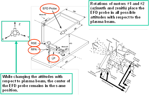
The rational of these tests is based on the fact that, in the ionosphere, the ion and electron currents are in general collected through different paths and variations of the probe potential can be induced by different orientations of the probe with respect to the orbital direction. For these tests a single EFD probe at the time is installed on a rotary mechanism capable to change its attitude with respect to the ion beam. The rotary mechanism allows two degree of freedom, thus simulating any possible orientations of the probe axis. During such tests the current-voltage characteristics of the EFD sensors and the plasma sheath impedance is measured as a function of different bias currents and ambient magnetic field conditions (intensity and orientation). A motorized system, capable to change the orientation of the EFD probe with respect to the ion beam has been specifically designed and realized for this test. The system operates in a way that, while changing the orientation of the boom axis, the center of the EFD probe remains in the same position within the chamber. This feature improves the separation of the effects due to the probe attitude changes from those associated to possible modifications of local plasma conditions. The rotary mechanical system allows to test one single EFD probe at the time. The probe current-voltage curve is measured by sweeping through a number of levels the EFD bias current generator, which is part of the electronics hosted within the spherical probe. The impedance of plasma sheath is measured applying a variable current signal and measuring the correspondent floating voltage variation. Such a measurement is performed at different DC current bias levels.
An additional Reference Spherical Electrode (RSE) with diameter Φ=6cm, is installed in a fixed position at 24cm from the EFD probe. This electrode is used to acquire the I-V curve, which the EFD probe characteristic is compared to.

Sketch of the EFD probe mechanical rotary system. Top panel gives a qualitative representation of the different EFD probe attitudes which can be set with respect to the ion beam.
2. Comparison between Italian (INFN) and Chinese (LIP) EFD
These tests imply simultaneous operation in plasma of two different sensors, one from the Italian side and the other from the Chinese side, placed at the same distance from the plasma source (about 3m). At such a distance, plasma parameters exhibit a quite good homogeneity and therefore the two sensors can be assumed embedded in the same environment. In these conditions the current-voltage characteristics and plasma sheath impedance are measured as a function of ambient magnetic field and input bias currents. In addition, the current-voltage characteristics measured for the two EFD sensors will be compared with that acquired by RSE (a reference electrode without stubs) placed in the vicinity of the sensors, thus evaluating the effect produced by the stubs on the EFD output voltage. The outcomes of these tests consist of:
- current-voltage characteristics
- electronic noise
- plasma sheath impedance
3. Plasma Test on Italian and Chinese EFD sensor pairs
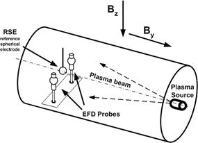
This group of measurements will be devoted to determine possible differential voltages arising between sensors in presence of high plasma density gradients. For this tests, two pairs of sensors are contemporary installed in the plasma chamber. One pair of sensors is from Italian side (INFN) and another pair is from Chinese side (LIP). Two sensors (one from INFN and the other from LIP) are placed in a fixed position at about 3m from the plasma source, whereas the other two will be moved within the chamber, using a sledge platform, to be placed at different distances from the plasma source (up to 1.5m), thus varying the plasma density they are embedded in. The tests will be carried out with the moving sensors positioned at 1.5m, 2m and 2.5m from the source (correspondent to 1.5m, 1m and 0.5m respectively, from fixed EFD probes). Such measurements will be all carried out with magnetic field equal to zero (B=0T), to avoid experimental complications possibly due to the plasma beam bending effect.
All tests are performed using the following plasma diagnostics devices:
- a single Langmuir Probe located in the middle between the two fixed EFD probes (at about 3m from plasma source)
- one Langmuir Probe and one RPA located about in the center of the sledge platform.
Thus each Plasma Diagnostics measurement will consist of acquisitions of Vpl, N, Te in a point close to the fixed EFD probes, plus one measurement of Vpl, N, Te and ion energy in the center of the sledge platform.

Positions of the two EFD probe pairs in the plasma chamber. Two EFD probes and one LP are fixed at about 3m from plasma source. Other two EFD probes, along with a LP and a RPA used for plasma diagnostics, are located on the moving sledge, which is successively positioned at 1.5m, 2m and 2.5m from the source.