The Electric Field Detector (EFD) is an instrument developed to measure the three components of the electric field by detecting the differences of potential between three different pairs of sensors.
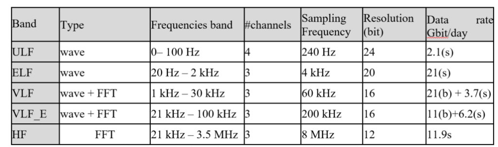
The signals from the sensors are processed firstly by an analog section and, lastly, a digital processing provides the last subdivision in five bands: ULFs (Ultra Low Frequency), ELF (Extremely Low Frequency), VLF (Very Low Frequency), VLF E (Very Low Frequency band Extended) and HF (High Frequency).
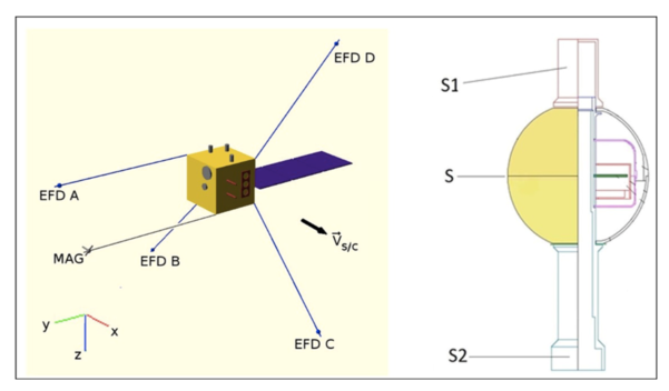
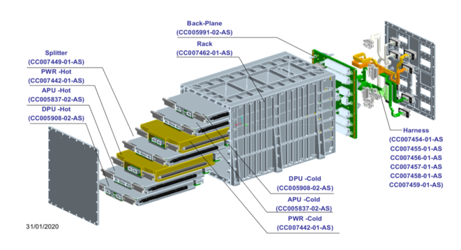
The detector consists of two parts (Figure 1):
- Four identical sensors called EFPs (Electric Field Probes). Each EFP, housed inside a spherical probe placed at the end of a satellite boom, has the task of detecting potential with high precision. A voltage adapter with high input impedance is the core of the front-end electronics of the sensor.
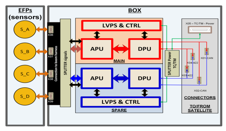
- A box, inside the satellite, which contains:
- the Low Voltage Power Supply (LVPS): power supply, housekeeping and TM/TC interface to satellite;
- the Analog Processing Unit (APU): a board devoted to the analog processing of signals and to the EFP control;
- the Digital Processing Unit (DPU): Digital Processing board, On-Board Data Handling (OBDH), Payload Control and Control;
- the Backplane for interconnections of the electronic boards including the electronics of the Analog Splitter: switching of signals/controls and power-supply lines of the EFPs between the main and spare electronics.
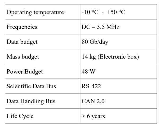
The main specifications of EFD-02 are reported in Table 1.
Table 2 shows the specifications of each EFD-02 band. The widening (w.r.t. Demeter) of the ULF and VLF bands (by also including the new VLF_E band) allow improving quality of data (bit and frequency resolution) and optimizing data-rate.
Bandwidth, sampling frequency and bit resolution have been adopted aimed at: i) improving the quality of the scientific information, ii) increasing the number of channels, iii) increasing the bit resolution and frequency resolution (also when FFT is applied).
The ULF band has been extended up to 100 Hz. This broadening allows the monitoring (with the highest resolution) of a larger variety of low-frequency waves and perturbations that can propagate inside the ionospheric cavity and through the ionosphere up to the satellite orbit, and that can provide insights on the lithosphere-atmosphere-ionosphere coupling mechanisms.
The ELF band (that has bit and frequency resolutions higher than those in the VLF band) has the upper frequency limit set to 2 kHz to have a significant overlap with the VLF band. In this way, for example, in the overlapping frequency range, the higher quality of ELF waveform can complement poorer information of the FFT in VLF band.
For the medium frequencies, the band has been extended in EFD-02 up to 1 – 100 kHz and split in two, by including a new band: 1 – 50 kHz (called VLF) and 21 – 100 kHz (called VLF_E). The lower VLF frequency (at 1 kHz) – with the, above mentioned, significant overlap with the ELF band – allows optimizing detection of whistlers and seismo-associated phenomena. At the same time, the widening of VLF band up to 100 kHz ensures that for FFT data the better frequency resolution will be available up to 100 kHz.
The total data budget available is 80 Gbit/day. EFD data will be collected in two different modes.
- Survey Mode: ULF and ELF waveform are continuously collected while VLF and HF bands are acquired as FFT. In order to reduce the data downloaded, spectrums are average values of 50 FFT acquired. Standard Deviation and Kurtosis complete the downloaded information.
- Burst Mode: in addition to data acquired in Survey mode, additional waveforms are collected for about two hours/day. During these periods the VLF-lower band is fully acquired and the extended VLF increases from 0.5% of Survey mode up to 16% in Burst mode.
Instrument Description:
The electronic box has been completely renewed since it has to host 8 boards and the relevant harness. The dimensions of the unit are 340x198x220 mm3. The payload is a box of aluminum alloy containing electronic boards bound to the base, which acts as thermal drainage. Thermal features of the electronic box have been obtained from a specific analysis performed simulating the power consumption of each electronic board.
This subsystem consists of the following elements (Figure 2):
- Mechanical enclosure: a milled aluminum box with chamfers for inserting wedge-locks, extraction areas, motherboard. The box will be made of lightweight alloy panels.
- Rigid flex backplane: a rigid flex interconnection backplane board which hosts several connectors. On the module side, it will mount standard connectors for the interconnection between modules while on the other side of a part of flex/capton interface with the satellite, it will mount non-standard out-of-the-box connectors.
- APU H module: main Analog Processing Unit (APU) with coaxial connectors on the front and high-speed connectors and suitable mechanical resistance on the The module will cling to the mechanics by dividing the wedge-locks that will also provide thermal contact (conduction cooled avionics architecture).
- DPU H Module: Digital Processing Unit (DPU) module interconnected to the backplane via VPX of similar size to the previous and similar architecture.
- APU C Module: spare DPU module in main/spare redundancy.
- DPU C Module: spare DPU module in main/spare redundancy.
- CTRL-LV H / C Module: Power distribution module of the same size as the previous modules.
The mass budget of this subsystem is 14 kg.
The Electric Field Probes (EFP) are the sensors of EFD located at the tip of four booms of 4.5 m each (Fig. 3). By collecting particles from ambient plasma, they reach the voltage called “Floating Potential” that is sensitive to environmental changes in terms of electromagnetic and plasma fluctuations. Even if probes shape and dimensions are the same of previous Electric Field Detectors, the EFP design has been updated in order to improve both mechanical and electrical performance.